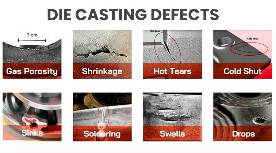
Die casting defects rarely appear without a reason. A cavity, crack, flash, or incomplete filling may look like an isolated quality issue, but the visible symptom often reflects a combination of die design, metal flow, temperature, pressure, and cooling conditions. Treating only the visible defect can therefore lead to repeated adjustments without resolving the underlying problem.
For manufacturers, a more effective approach is to connect each defect with its location, appearance, process history, and internal structure. By combining these clues, it becomes possible to narrow down the root cause and determine which process variable or tooling condition needs attention.
Why Identifying the Defect Is Only the First Step
Naming a defect is useful, but it does not explain why it occurred.
For example, internal voids may indicate gas porosity or shrinkage, while a crack-like line may result from a cold shut or an actual structural crack. These defects can appear similar during visual inspection but require very different corrective actions.
A reliable diagnosis should therefore answer three questions: Where did the defect occur? What does its structure indicate? Which process conditions could have created it?
This approach helps prevent unnecessary changes to injection speed, temperature, or pressure when the actual issue originates from die design or localized heat accumulation.
Start With the Location and Appearance
The position of a defect often provides an important clue about its origin.
Defects near the gate may be associated with high-velocity metal flow, turbulence, erosion, or localized thermal conditions. When defects repeatedly appear around the parting line, die alignment, venting, or flash formation deserves closer examination.
Thin sections require sufficient metal flow and heat retention to fill completely. Misruns or cold shuts in these areas may indicate insufficient filling capability or unfavorable flow conditions. In contrast, defects around thick sections can be related to localized solidification and shrinkage because thicker material generally retains heat for longer.
Surface appearance also matters. A raised area that becomes visible after heat treatment may indicate trapped gas and blistering, while thin excess metal along the parting line may point toward flash or die mismatch.
Connecting Die Casting Defects With Their Root Causes
Different symptoms can point toward different mechanisms. Round or relatively smooth internal voids are commonly associated with gas porosity, particularly when air or gas becomes trapped during filling. Irregular internal cavities may instead indicate shrinkage during solidification.
Thin fins extending from the casting are characteristic of flash, while incomplete edges may indicate a misrun caused by insufficient filling. Crack-like lines require more careful examination because cold shuts and cracks can have different origins and implications.
Surface sticking may suggest soldering between the molten alloy and die surface, particularly under unfavorable thermal or material conditions. Blisters that become apparent after heating can be associated with subsurface gas that expands during thermal exposure.
The important point is that the same visual inspection should not automatically lead to the same corrective action. Internal inspection and process records are often needed to distinguish similar-looking defects.
Use Process Parameters as Diagnostic Evidence
Process parameters provide another layer of evidence when investigating die casting defects.
Injection speed affects metal flow behavior, turbulence, and filling time. Metal temperature influences fluidity and solidification behavior, while die temperature affects how quickly the alloy loses heat during filling.
Pressure also matters because insufficient or unstable pressure can influence cavity filling and internal density. Filling time can reveal whether the casting is experiencing premature solidification or an excessively aggressive filling pattern. Cooling conditions should also be reviewed, particularly when defects concentrate around thick sections or specific thermal zones.
Instead of changing several parameters simultaneously, manufacturers can compare defect locations with process data and adjust one relevant variable at a time. This makes it easier to determine whether a parameter change actually addresses the root cause.
Separate Defects That Look Similar
Some die casting defects require additional investigation because their external appearance can be misleading.
Porosity and shrinkage are a typical example. Both can create internal voids, but their shapes and locations may differ. Gas porosity is often associated with relatively rounded voids, while shrinkage tends to produce irregular cavities in areas that solidify later.
Cold shuts and cracks can also appear as lines on the casting surface. A cold shut is generally associated with incomplete fusion between advancing metal fronts, whereas a crack represents a fracture that may develop during solidification, cooling, or subsequent processing.
Flash and parting-line mismatch should also be distinguished. Flash is excess metal that escapes along a die interface, while mismatch involves dimensional displacement between die halves. Checking the parting-line geometry and comparing multiple castings can help determine whether the problem is process-related or tooling-related.
Combine Inspection With Root Cause Analysis
A structured investigation is more reliable than relying on visual judgment alone.
The 5 Whys method can help trace a recurring defect from the immediate symptom to a process or tooling cause. Production data can reveal whether the defect correlates with particular machines, dies, shifts, materials, or parameter ranges.
For internal defects, X-ray inspection can provide a non-destructive view of porosity and other internal anomalies. CT scanning can provide more detailed three-dimensional information when the location and morphology of an internal defect need to be analyzed. Metallographic examination can further reveal internal structures and help distinguish different failure mechanisms.
After identifying a likely cause, controlled trial adjustments can verify the diagnosis. The objective is not simply to make one batch pass inspection, but to establish a repeatable process window.
A More Systematic Die Casting Troubleshooting Workflow
An effective troubleshooting process can begin with defect classification and location mapping. The next step is to compare the defect pattern with tooling geometry and production parameters. If the evidence points toward an internal issue, non-destructive inspection can provide additional information before destructive analysis is considered.
Once several possible causes have been identified, process history and inspection results can be combined to narrow the possibilities. Targeted adjustments can then be tested under controlled conditions, with the resulting casting quality compared against the original condition.
HordRT applies this engineering-oriented approach to die casting projects, combining tooling development, die casting production, quality inspection, and process analysis. Its experience across mold design and casting production allows potential issues to be considered earlier rather than treating quality problems only after mass production begins. For projects where dimensional consistency, surface quality, internal integrity, and production stability all matter, this integrated capability can make defect diagnosis more structured and efficient.
Turning Defect Analysis Into Process Improvement
Die casting defects are often the visible result of a deeper interaction between tooling, material, machine settings, thermal conditions, and metal flow. Identifying the defect is therefore only the beginning.
By studying where a defect occurs, examining its physical characteristics, comparing relevant process parameters, and validating potential causes through inspection and controlled trials, manufacturers can move from repeated correction to systematic root cause analysis.
With integrated die casting and tooling capabilities, HordRT supports this process from mold development through production and quality evaluation. The goal is not simply to remove an individual defect, but to understand why it occurred and create a more stable manufacturing process for future production.
